MY PLAY Cell 1-Top
Installation and Start-up Guide
1. Product Description
A ceiling-mounted RFID reader that integrates two Myruns components to ensure optimal
reading results: the MB R1 reader and the MB A3 antenna. It features SMA connectors that
allow for the control of up to three "slave" versions of the product.
2. Package contents
Please ensure that the package you receive contains all the items listed below.
- MP Cell 1-Top Device
- 24V power cable
* An Ethernet cable, not included in the package, is required for setup and connectivity during installation of this product.
Coaxial cables for connecting the slave devices are not included in the package. Low-loss coaxial cables are recommended.
Recommended reference: LMR240
* If you purchased the cable-suspended version of the MP Cell 1-Top, please note that suspension cables are not included. Refer to chapter 3.2 of this manual for compatible cable options.
* If you purchased the MP Cell 1-Top version with VESA tube mounting, please note that you will need M4 screws to attach the device.
3. Installation and commissioning
There are two versions of this product with respect to its installation. Verify if the product's suspension area corresponds to the VESA tube insertion area (see the back of the product):
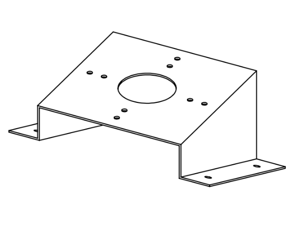
If you do not see this structure on the back of the product, check the four "legs" of the product, where you will find an anchoring structure like the one shown in the image:
3.1. Option 1: Tube
If you have confirmed that the version you purchased includes the VESA mount, proceed with the installation by following these steps:
- Secure the VESA 100x100 or 75x75 fitting to the ceiling using screws and expansion anchors. This fitting must be the precise length needed to position the device at a height of 3 meters.
- Identify the mounting holes on the product. They correspond to the VESA 100x100 and 75x75 mounting standards.
- Use M4 screws for screwing (not included in the package).
3.2. Option 2: Suspension cables
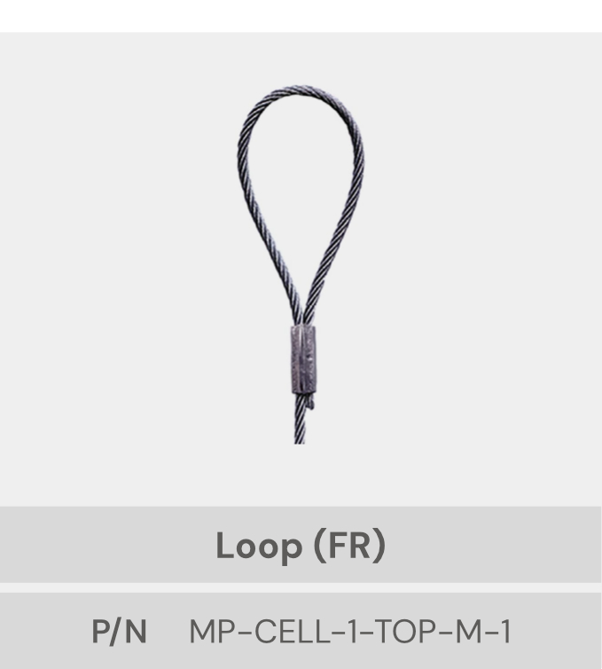
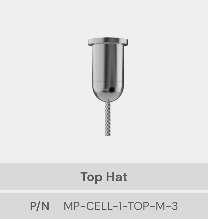
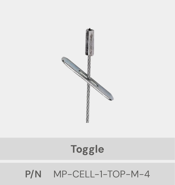
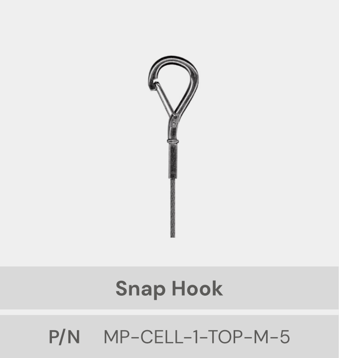
For the cable-suspended version, there are five suspension cable options that can be attached to the four mounting points on the MP Cell 1-Top (the “legs”). The cable is not included with the product. Below are the options you can purchase or that your supplier or customer can provide:
Follow these steps to complete the installation:
- The ceiling mounting must be adequate and it must be installed on a reliable substrate to withstand the working load.
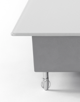
- Insert the metal cable only into the upper, "bulged" part of each support located at the corners.
- Trim or cut the metal cable only after inserting it into the unit, never before, as this could affect its operation.
- To adjust the height, press the buttons and the unit can be moved both down and up.
- It is essential to remove or secure the load before making any adjustments.
- Make sure the steel cable comes out clearly from the unit.
- Always ensure that at least 25 mm of cable protrudes from the side of the product after installation.
- The cables coming out of the device must be guided by one of the 4 cables.
3.3. Connections
- Connect the power cord to the socket provided by the customer.
- Connect the ETHERNET cable to the network socket provided by the customer (ETHERNET cable not included).
- Connect the USB cable to proceed with the testing setup and sending of readings.
3.2. Test reading
Follow these steps to verify that the MP CELL 1 - Top Master device is correctly reading the RFID tags:
STEP 1: Connect the device
- Connect the device to a power source using the 24V cable included in the package.
- Connect the device to a PC using the USB C to USB A cable (this cable is not included in the package).
- Connect the reader to a network socket using an RJ45 cable (this cable is not included in the package).
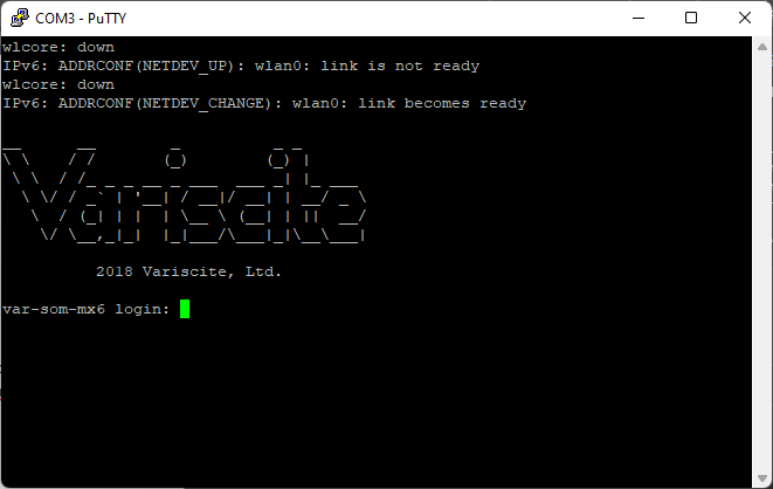
STEP 2: Connect the device to your local network.
Use a software tool to emulate a terminal (PuTTY, MobaXterm, or similar). This
example uses PuTTY
.
Follow these steps to connect the MP
Cell 1-Top to the local network from the terminal.
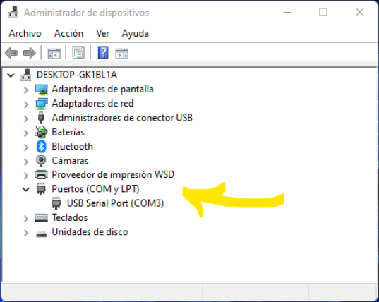
- Access the Device Manager on the PC to which the device is connected and locate the COM and LPT ports. In this section, you will find the COM port that the PC has assigned to the Myruns device.
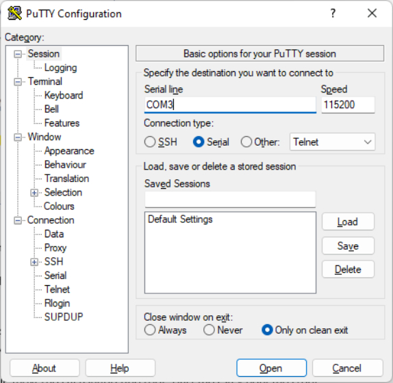
- Next, return to your terminal application and specify the COM port in the corresponding field. In the "speed" field, specify 115200.
- In the terminal window that opens, press the "Enter" key and then log in with this username and password: user/user
-
Next, we'll need to switch to the root user. We type:
suwe type the username:rootand finally, the password:root
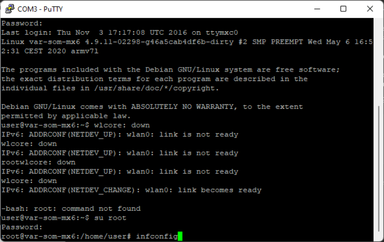
STEP 3: Open the Myruns software
At this point, we will have accessed the reader with administrator privileges
through the terminal. We only need to find the assigned IP address to access it from
a web browser. To do this, we type the following in the terminal:
ipconfig
We locate the
dynamic IP address (192.168.1.X)
, copy and paste it into the browser,
and press Enter. This will take us to the reader's software console.
STEP 4: Read the test
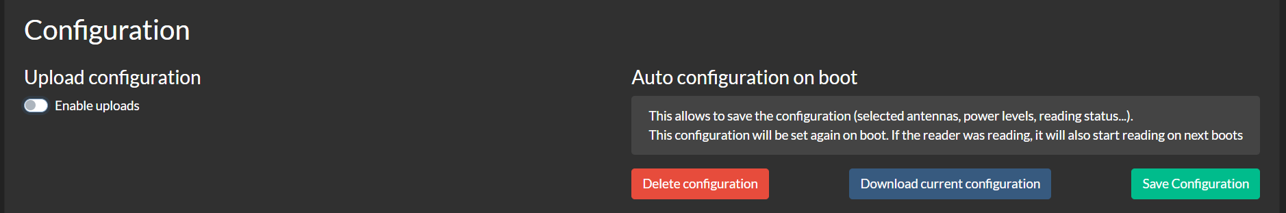
- On the console, we can start the system and verify the reading.
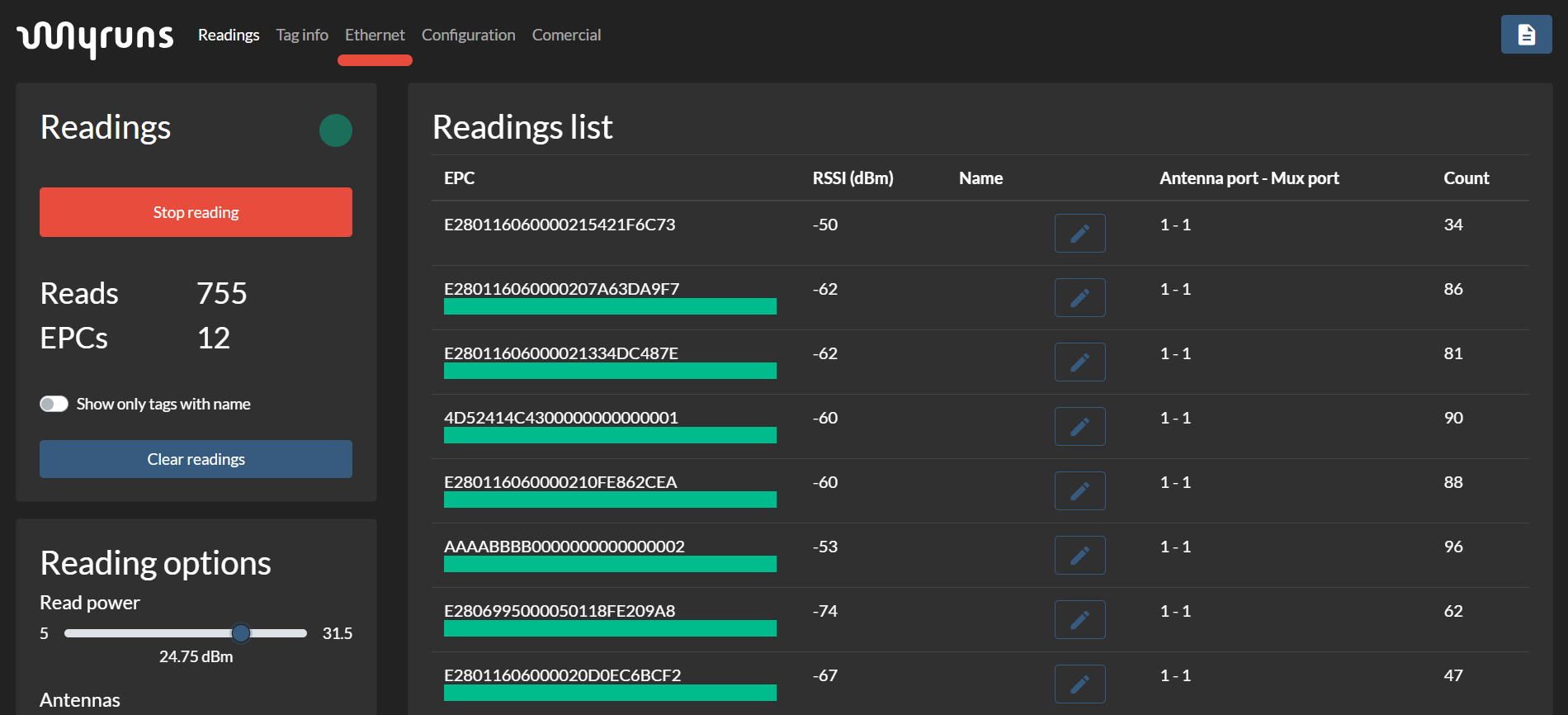
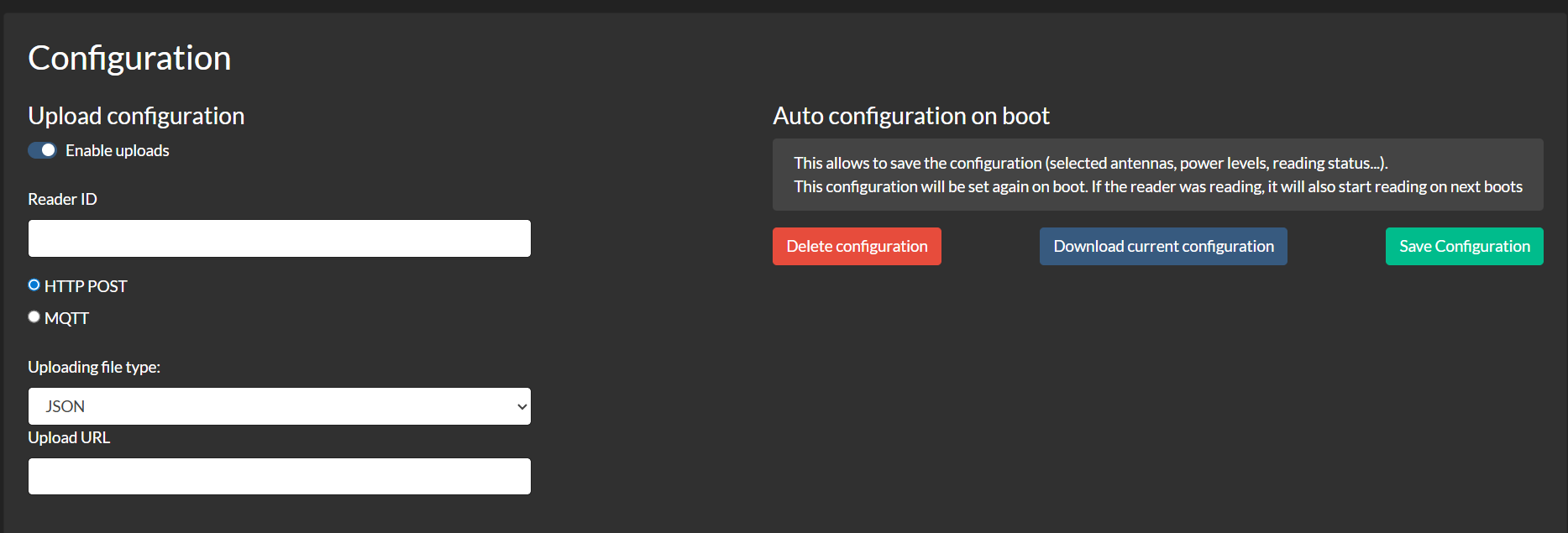
- In the settings tab, we can also find the GPIO manager and the reading submission.
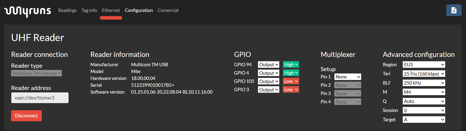
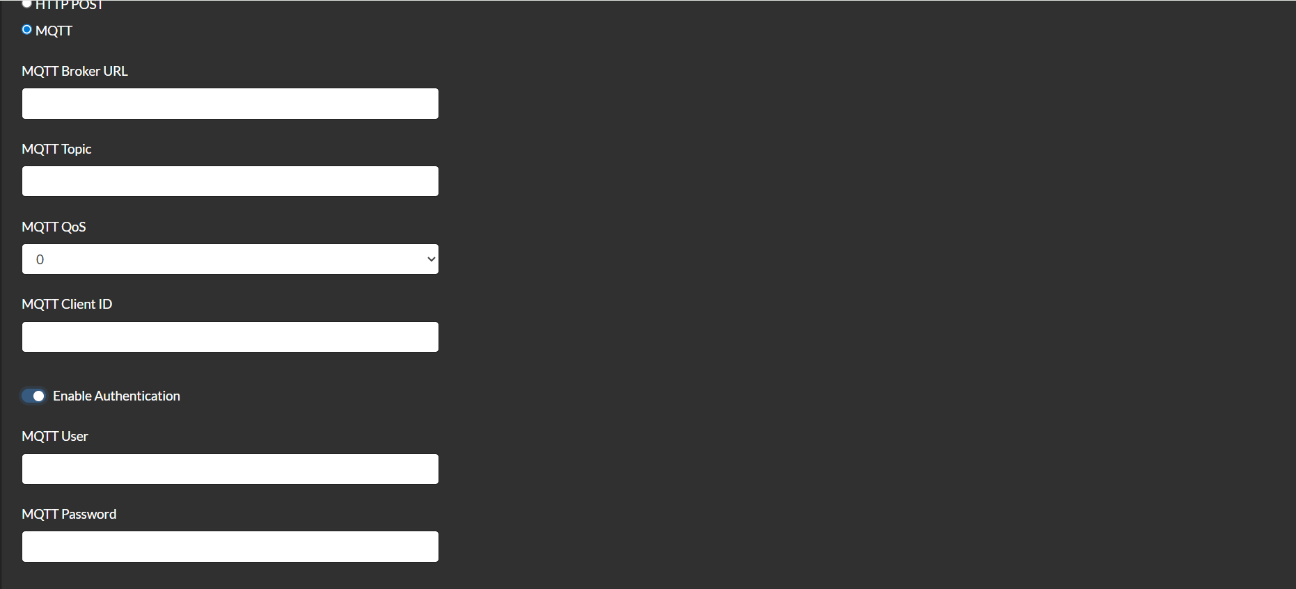
- Readings can be sent via HTTP Post or MQTT.
4. Troubleshooting
If the MP CELL 1 - Top Master device does not function correctly during the testing phase, follow the steps below to identify and troubleshoot any problems:
1. Check the device's power
supply.
Ensure the device's power supply is
properly connected.
2. Check the USB and/or Ethernet
cable connection.
Try connecting the device to a
different USB port on your PC. If no ports are available, try testing on another
computer to rule out system issues. Repeat this process for the Ethernet cable and
socket.
3. Replace the USB and/or Ethernet
cable.
Replace the supplied cable with one
of the same specifications (USB Type-A to Type-C) to rule out cable failure. Repeat
this process for the Ethernet cable.
4. Test another MP CELL 1 - Top
Master device.
If you have another device, repeat
the test using the same original port and cables to determine if the problem is with
the device's hardware.
5. Contact technical support.
If the problem persists after
performing all the above tests, contact Myruns technical support for assistance.